Core Technologies
Powerful step to the future gas turbine total service provider
Gas Turbine high temperature specialty company SUNG-IL TURBINE P&S

Combustor hot gas path part production technology
[ Overview ]

Combustor hot gas path part production technology

홈 Core Technologies Combustor hot gas path part production technology Overview

Hot gas path parts for combustor Production technology overview

Forming

Equipped with various forming technologies and facilities for spinning, press, rolling, bending, etc.
Conducts forming process for various shapes and sizes.

Welding

Equipped with multiple super alloy welding and bonding technologies.
The mechanical feature of heat-resisting alloy can remain after welding process.
Manufactures hot gas path parts made of super alloy for gas turbine combustor.

Heat Treatment

Has heat treatment technology applicable to various materials including super alloy through large-size electric heating furnace and vacuum heating furnace.
Performing heat treatment to remove stress triggered during forming, welding, etc., and to maximize the characteristic of each material.

Strengths of Combustor Hot Gas Path Part Technology

  1. 01Swift and precise production.
  2. 02Internal TBC applied.
  3. 03A variety of cooling technologies are employed.
  4. 04Made of super alloy.

Types of Hot Gas Path Parts for Combustor

  • SA11N / NM
  • 7FA/7FA+e
  • 501D/F
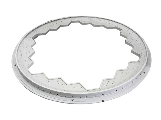
Hot Gas Casing Picture of ProductHot Gas Casing
Purpose
Sending combustion gas to 1-stage vane
Development Period
’02. 10. 1 ~ ‘05. 9. 30(36 months)
Remark
- consisting of 2 components of upper part and lower part
- Divided into 2 with the rotor in the middle. The thermal barrier coating is applied to the upper part.
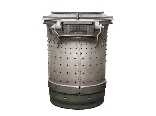
Inner Liner Picture of ProductInner Liner
Purpose
Sends combustion gas to hot gas casing
Development Period
’01. 5. 1. ~ ‘02. 3. 31.(11 months)
Remark
In a large cylinder shape, the connecting part to hot gas casing is shaped like nozzle.
Support Cylinder Picture of ProductSupport Cylinder
Purpose
Structure where thermal barrier tiles are installed.
Development Period
‘97. 6. 26. ~ ‘98. 9. 25.(15 months)
Remark
Located in the upper combustor.
Shielding Cone Picture of ProductShielding Cone
Purpose
Props up burner.
Development Period
‘04. 11. 1. ~ ‘06. 3. 31.(15 months)
Remark
Located in the upper combustor.
Receives compressed air and then sends it into combustor.
Cap Assembly Picture of ProductCap Assembly
Purpose
Fixing and propping up fuel nozzle.
Preventing from combustion liner in the middle of combustion.
Development Period
‘09. 6. 1. ~ ‘11. 11. 30.(30 months)
Remark
-
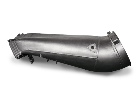
Transition Piece Picture of ProductTransition Piece
Purpose
Sending the premixed combustion gas in combustor basket toward 1-stage vane.
Development Period
‘07. 8. ~ ‘11. 7.(60 months)
Remark
Thermal barrier coating is applied as protection against to stop the degradation and oxidation of material.
Combustion Liner Picture of ProductCombustion Liner
Purpose
A space where the combustion of air & fuel premixed in and supplied from fuel supply system happens.
Distributing combustion gas to turbine blade and vane.
Development Period
‘07. 8. ~ ‘11. 7.(60 months)
Remark
Made of nickel-based super alloy.
T/P(W501D5) Picture of ProductT/P(W501D5)
Purpose
Sends the combustion gas premixed in combustor basket to 1-stage vane.
Development Period
‘12. 9. 1. ~ ‘14. 8. 31.(24 months)
Remark
Thermal barrier coating is applied to stop the degradation and oxidation of material.